


Fire Alarm Systems
FIRE ALARM CONTROL AND INDICATING PANEL STANDARD OF MANUFACTURE
The fire Alarm control and indicating equipment for this project comply fully with the requirements of B.S. 5839 part 4 1988 and meet the requirements of the Loss Prevention Certification Board (LPCB) of the U.K, as suitable for installation in fire detection systems designed to B.S. 5839 Part 4 of 1988
GENERAL REQUIREMENTS OF THE CONTROL PANEL
The fire alarm control and indicating panel shall be the central processing unit of the whole fire detection and alarm system receiving signals from detectors, and providing visual and audible information to the user, and initiating automatic alarm response sequences and providing the means by which the user interacts with the system.
The Panel is easily configurable to meet the exact detection zone and output mapping requirements of the user.
The control and indicating box pane: incorporates a key switch to prevent unauthorized use of manual controls.
The panel has the ability to drive repeater panels connected to it.
The components of the control panel shall be housed in a metal box with lockable device to prevent unauthorized use and to afford a minimum protection of IP43
BASIC FUNCTIONS OF THE ALARM CONTROL PANEL
The fire alarm control and indicating panel shall monitor the status of all devices in the fire alarm system for short-circuit fault, unauthorized device removal, or exchange.
It shall monitor the status of all internal connections and interfaces including charger and batteries
The control panel shall provide the following visual indications
POWER ON : Green LED INDICATOR
FIRE ALARM : Dual Red LED INDICATOR
FAULT : Yellow LED INDICATOR
DISABLED/ISOLATE : Yellow LED INDICATOR
FREE ZONES : Red LED INDICATOR
The fire alarm control panel shall provide a set of push bottom controls to enable a authorized operator perform the following
EVACUATE: Actuates all alarm sounders in the system
SILENCE: Stops all currently actuated alarms
RESET :Returns the control panel to quiescent state
The fire alarm control panel shall provide facility to manually check all the LED indicators.
The facility shall be clearly marked LAMP TEST and shall be available at all times.
The control panel shall be capable of monitoring and controlling emote site devices such as door release devices and relays for the control of plants and equipment.
Additionally, the control panel shall provide outputs for the activation of emergency lighting if any in the event of mains failure.
ALARM OUTPUT FUNCTIONS OF THE CONTROL PANEL
The fire alarm control and indicating equipment shall provide the necessary outputs to delay the separately operate to (2) monitored circuits of common system sounders.
Each output shall be capable of driving a sounder load up to 1Amp.
The control panel shall be able to monitor the integrity of the sounders.
The panel shall have a facility to delay the initiation of the alarm to a preset time, but it shall however not inhibit alarms generated by manual call points in the system
SUPERVISION AND FAULT REPORTING
The control panel shall monitor all systems components and interconnectors such that in the event of failure occurring which prevents correct operation of the alarm function, a FAULT indicator will give light to indicate a fault condition with the sounding of an internal buzzer.
The fire alarm control panel shall provide detection zone and sounder output monitoring as well as common fault monitoring through a common fault and change over relay outputs rated at 1A @4vd.c
The common fault relay shall be normally energised and shall de-energize to signal zone faults, mains failure, battery/charger, failure earth and supervised output fault.
ZONE ISOLATE AN DSOUNDER DISABLED FACILITY
The fire alarm control panel shall have a facility to allow zones and sounder circuits to be individually isolate to enable servicing be undertaken.
Isolated zones and circuits shall be individually indicated on the display of the fire alarm control panel.
ONE MAN TEST FACILITY
The control panel shall have a one man test facility to enable an Engineer carry out a test of the fire alarm system alone. This facility must leave the panel functional on all but the zone under test. An alarm condition in a zone test shall be indicated by the sounding of the alarm for a second “On” and “Off”
AUTOMATIC DETECTORS
HIGH PERFORMANCE OPTICAL SMOKE DETECTROS
The automatic smoke detector specified for installation in the fire detection and alarm system for this project shall be the HIGH Performance Optical Detector (HSOSD).
It shall be designed and manufactured in accordance with the functional requirements of BS. 5445 PART 7 1984 (EN54 part 7) and shall be capable of detecting combustible gases emanating from ides.
The hugh performance optical smoke detector shall have sensibility sufficient to be classifies as “B” or better in BS. 5445 part 9 1984 (EN54 part 9) test fires TF2 to TF5 inclusive.
They shall be approved and listed by the Loss Prevention Certification Board (LPCD)
In addition the High Performance Optical Smoke Detector shall meet the following requirements:
1. Employ the forward light-scatter principle using optical components operating at wavelength of 4.3mm
2. Shall not generate alarm from a rate of rise of temperature or absolute temperature alone
3. Shall incorporate screens designed to prevent all but the very small insects from entering the sensing chamber to cause contamination
4. It shall have high resistance to contamination and corrosion
5. It shall include RFI screening and feed-through connecting components to minimize the effect of radiated and conducted electrical interferences
6. It shall incorporate a LED clearly visible from the outside to provide indication of alarm actuation
INFRA RED FLAME DETECTOR
The infra red flame detector shall be approved by the Loss Prevention Certification Board (LPCB) of the UK, and shall be capable of detecting infra-red radiations produced by flaming fires involving carbonaceous materials such as petrol, alcohol, N-heptane, Kerosene, Ethylene, Diesel Oil, etc.
It shall be able to detect a fuel fire of 0.1 square meters produced by the above fuels.
It shall employ narrow band optical filters that block unwanted radiation such as that emanating from the sun or tungsten filament lamps.
It shall be sensitive to the modulation of received radiation in a small range of frequencies corresponding to the flicker of flames, and having a high resistance to contamination and corrosion.
It shall additionally have RFI screening to minimize the effect of radiated and conducted electrical interferences.
The infra-red flame detector shall incorporate a LED clearly visible from outside to provide indication of alarm actuation.
HEAT DETECTOR
The heat detector specifies for installation in this project shall be the Rate of Rise type and shall meet the following criteria
The heat detector shall meet the requirements of BS. 5445 part 8 for heat detectors designed for high ambient temperatures.
It shall be suitable for installation in a kitchen, where temperatures are normally high.
It shall be capable of detecting rapid rise of temperatures over and above the normal high ambient temperature and to operate at a pre-determined upper fixed limit.
It shall be approved and listed by the LPCD of UK
In addition, the heat detector shall meet the following requirements:
1. Employ two heat sensing elements with different thermal characteristics to provide a rate of the dependent response. The temperature sensing elements and circuitry shall be coated with epoxy resin to provide environmental protection
2. Include RFO screening and feed-through connecting components to minimize the effects of radiated and conducted electrical interferences.
OPTICAL BEAM SMOKE DETECTOR
The Optical beam smoke detector shall meet the specifications set forth below:
It shall be capable of detecting the presence of smoke in large open interiors, and shall project modulated infra-red light beam from a transmitter unit to a receiver unit.
The receiver signal be analyzed and in the event of smoke being present for a pre-determined period,, an alarm condition shall be generated.
The fire alarm output of the beam detector shall be activated in the event of smoke reducing the signal strength between 40% and 90% for a period of approximately 5 seconds
The optical beam smoke detector shall meet the following requirements:
1. In the event of the of power failure at the transmitter unit, or of the transmitter signal shall reduce by 90% for a period of 1 second, then a fault condition shall be indicated at a control panel. He transmitter unit of the beam shall automatically reset about 5 seconds after the fault condition no longer exists.
2. The beam detector shall incorporate an automatic gain control (AGN) circuitry capable of providing compensation for long term degradation of signal strength caused by component ageing or build up dirt on the optical surfaces of the transmitter and receiver and lenses.
3. The optical beam smoke detector shall meet the requirements of BS. 5445 part 5 for detectors suitable for both normal and high ambient temperatures and be LPCB approved and listed.
4. The receiver unit of the beam smoke detector shall incorporate an alignment fault lamp clearly visible from the outside to provide indication of both alignment and fault condition.
BREAK GLASS MANUAL CALL POINT
The break glass manual call point specified fro this shall be manufactured to BS. 4558 part 2 of 1988.
The break Glass manual call point shall incorporate frangible glass front cover that can be easily broken by thumb pressure to enable the completion of the electrical switch and to operate the call point
Manual Call Point shall meet the following additional requirements:
1. Not be spaced more than 30 meters apart
2. Use the same method for operation (thumb pressure)
3. The time between operation and the sounding of the alarm should not be more than 1 second
4. Be mounted at the height of 1.4m above the finished floor level
5. Be mounted free of any obstructions
6. Be mounted against a contrasting background for easy identification
FIRE ALARM SOUNDERS
There shall be installed in the automatic fire alarm system electronic fire alarm sounders.
They shall be positioned at the point indicated by the design drawings.
The operation of the fire alarm sounders shall be initiated by the fire alarm control and indicating panel upon receipts of signals for the system automatic detectors and manual call points.
The fire alarm sounders may also be sounded manually from the control panel by the use of the EVACUATE push bottom.
CABLES AND CONDUITING
Communication between the fire alarm and indicating panel and field components shall be by radio signals.
The cables to be used for the wiring of the fire alarm control and indicating panel and the local wiring of the detectors meet generally the requirements of BS. 5839 part 1; 1988-fire detection and alarm system in buildings.
For this installation stranded copper cables of 2.5mm cross sectional diameter insulated and sheathed and additionally protected by electrical grade pvc conduit pipes shall be used for the system wiring
POWER SUPPLY
Power supply to the automatic fire detection and alarm system shall be taken from the nearest electrical distribution panel to the fire alarm system control and indicating panel.
However, this shall first be fed to the standby power system rectifier/charger which shall concert the 240volts a/c to the 24vd.c which the fire alarm control panel and system components require.
In addition to the public ECG means supply, there shall be a standby power supply system to control of approximately rated lead/acid maintenance free combination batteries which shall have enough capacity to supply the system’s requirements for 72 hours and then after, be able to support the system alarm requirement for 30 seconds.
The standby power shall be housed separately and located close to the fire alarm control panel
COMMISSIONING
The fire alarm detection and alarm system shall be commissioned according to the manufacturer’s regulations and instructions as contained in the technical manual issued with the product.
The commissioning procedure shall be supervised by the Project Engineer and officials of the Ghana National Fire Service.
-
![PACK HEATER]()
![]()
- New
PACK HEATER
MODEL: LC- MCT0080
-
![CHAIR, QUADRICEPS]()
![]()
- New
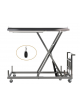
CHAIR, QUADRICEPS
MODEL: LC- MCT0109
-
![TREADMILL]()
![]()
- New
TREADMILL
MODEL: LC- MC02
-
![ULTRASONIC THERAPY DEVICE]()
![]()
- New
ULTRASONIC THERAPY DEVICE
MODEL: LC-3120TCM
-
![WOBBLE BOARD]()
![]()
- New
WOBBLE BOARD
MODEL: LC- MCT0038
-
![TRANSCUTANEOUS ELECTRICAL...]()
![]()
- New
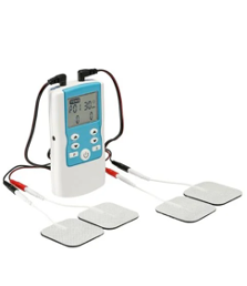
TRANSCUTANEOUS ELECTRICAL NERVE...
MODEL: LC-PPM002
-
![DIGITAL SPHYGMOMANOMETER,...]()
![]()
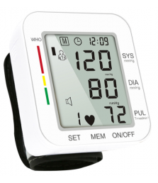
- New
DIGITAL SPHYGMOMANOMETER, WRIST...
MODEL: LC- MC009
-
![BARS,PARALLEL,ADJUSTABLE]()
![]()
- New
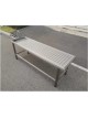
BARS,PARALLEL,ADJUSTABLE
MODEL: LC- MCT0269
-
![CARDIOTOCOGRAPHY UNIT]()
![]()
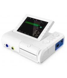
- New
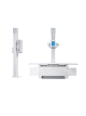
CARDIOTOCOGRAPHY UNIT
MODEL: LC- G008SMC
-
![INFANT INCUBATOR]()
![]()
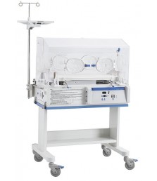
- New
INFANT INCUBATOR
MODEL: LC-A001-NB
-
![BILIRUBINOMETER]()
![]()
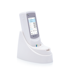
- New
BILIRUBINOMETER
MODEL: LC-A001MB
-
![BABY (TREASURE) COT]()
![]()
- New
BABY (TREASURE) COT
Model: LC-110BC-GA


Products
Our company
payment method
![]()
![]()
![]()